
I have been working on an emulator for the Super Nintendo (SNES), in Rust. Although it performed fine in a single-threaded design on a modern system, I wanted to parallelize work within the process to give the emulator some more resource headroom, to make it perform well on older/slower multi-core systems and to have enough resources available for implementing audio and speed-up modes later.
The SNES Picture Processing Unit
At the time of SNES’ introduction, in 1990, its graphics were revolutionary, only rivaled by the Sega Genesis / Mega Drive at that time. At the core of these graphics is the SNES PPU (Picture Processing Unit).
Depending on the configuration, it could handle up to 256 colors, draw 4 background layers on top each other, produce translucency and other effects using Color Math and rotate/scale in the famous mode 7.

Transluceny using color math in Super Mario World
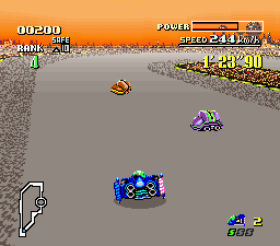
Mode 7 used for the track in F-Zero
The SNES main CPU, a WDC 65C816 - the 16-bit successor to the 6502 used in the NES, configures the PPU through registers and several different types of memory:
- 32KB of VRAM (Video RAM), where tile maps and tile graphics data resides.
- 528 bytes of OAM (Object Attribute Memory), where sprite attributes reside.
- 512 bytes of CGRAM, color palette memory.
The PPU produces pixels at the frequency of the TV set connected to it, e.g. 50 frames per second for PAL and 60 frames per second for NTSC. There was no double buffering, so the PPU and CPU needed to keep up with the pace of the signal the SNES had to provide to the TV. A frame was built up in horizontal lines, called scanlines. These scanlines are built from left to right. As the electron beam in the TV advanced, the SNES had to keep providing color data for each pixel (or ‘dot’).
Fortunately, there was also some small breathing room in which the CPU had some time to make changes. At the end of each scanline, there is a small time period in which the PPU is waiting for the next scanline to start. This period is called ‘horizontal blank’ or HBlank, for short.
At the end of the frame, there is a longer time period in which the PPU is idle, waiting for the next frame to start. This period lasts for many scanlines and is called ‘vertical blank’ or VBlank.

There’s some things the game can or cannot do when the PPU advances through an area:
- During HBlank and VBlank, the game can access ALL the PPU memory and registers.
- While drawing the visible area, the game CANNOT access any of the PPU memory but it can access most of the registers.
Performance of an emulated PPU
Most of the work of rendering a frame consists of looking up which tiles to draw where and decoding the tile data which is organized in bitplanes and can be flipped, drawn using different palettes, etc. An image can consist of up to 4 background layers and sprites. There is a set of priorities in tiles and sprites that decide in which order things are drawn so they overlap as desired. For example, a fully utilized mode 0 frame requires a total of 12 passes to render.
On top of that, there’s color math. For color math, ANOTHER frame, usually with different layers selected, is produced using the same process. This frame is called the subscreen. Then, each subscreen pixel is substracted or added to pixels on the main screen, which produces the effect. The same fully utilized mode 0 frame would then require 24 passes to render, and another pass to apply the color math operation for each pixel.
Now; as we saw before, the game can change the PPU configuration at each scanline (actually also throughout the scanline, but this is rare enough not to care about). The game can change anything; even switch from e.g. mode 3 to mode 7 halfway through the frame and back, change scroll registers or the position of sprites. The SNES even has a mechanism specifically designed for per-scanline changes, called HDMA. The only limit is the time available on HBlank. Therefore, we need to render one scanline at a time and run the CPU in between so it can perform these changes.
For a modern PC and an emulator that is compiled to native code, it’s no big deal. However, on smaller, more resource constraint devices, this requires some optimization.
Parallelizing the renderer
On one side of the PPU, we have the CPU updating registers and memory and on the other we render the image and send it to the display. Based on this, we can split the data in two parts:
- A set that is writable and contains every single register and memory type, as required by the CPU.
- A set that is read-only and only consists of data required by the rendering process.
The second set basically consists of:
- All PPU registers except the memory access ports and things like the H/V latches and the high-speed multiplication unit,
- All memory (read-only): VRAM, OAM, CGRAM.
Additionally, the first set contains the things only the CPU needs:
- The memory access ports for writing to the PPU memory,
- H/V latches,
- Interrupt triggering related data,
- Any timing related things.
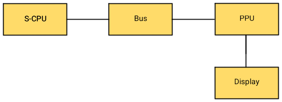
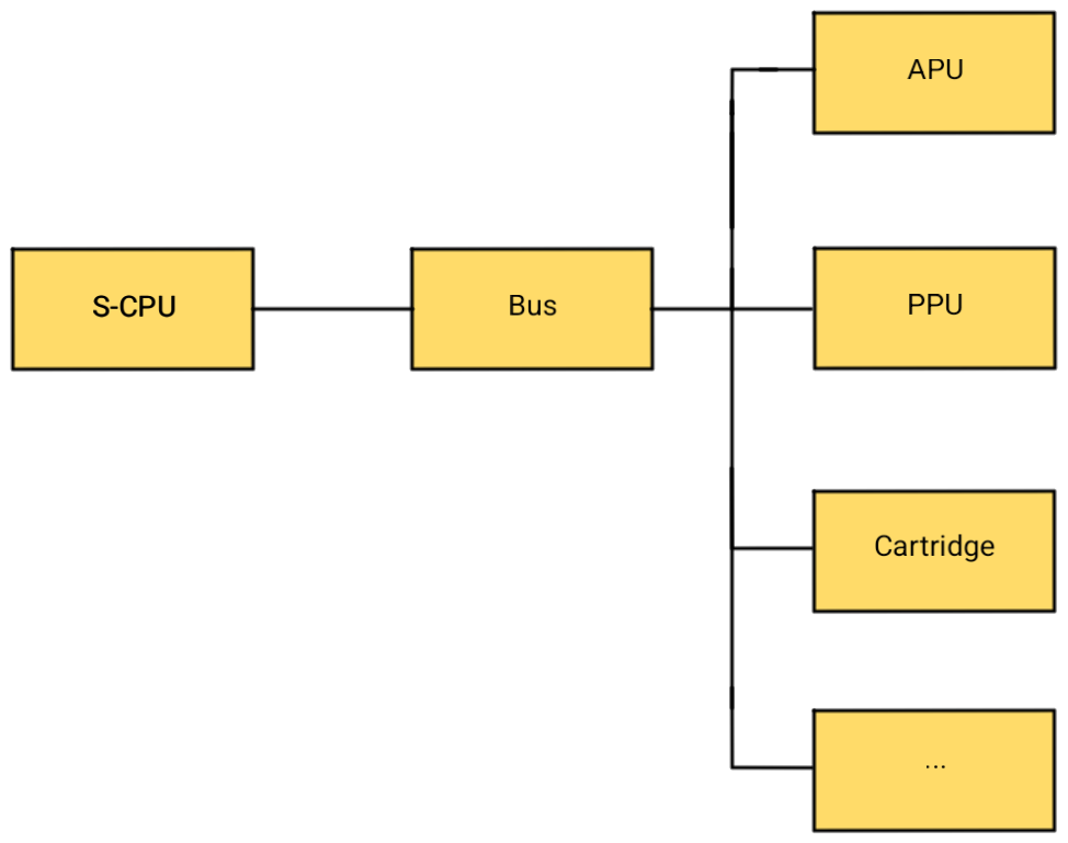
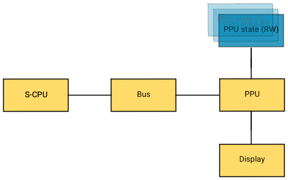
My emulator architecture models the main S-CPU as an object which is connected to a bus, which in turn contains all the memory-mapped peripherals:
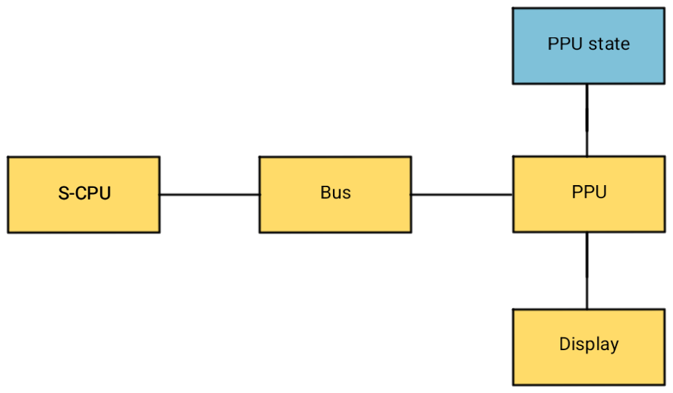
We can separate all the data relevant for the rendering process that can be used read-only into a ‘PPU state’ and progress from there. The ‘PPU’ object will expose the first set of data to the CPU and route the second set to the ‘PPU state’.
pub struct PPU<TRenderer: Renderer> {
	state: PPUState,

	// ...
}

pub struct PPUState {
    pub(super) vram: Vec<VramWord>,
    pub(super) cgram: Vec<CgramWord>,
	// ... more memory ...

    pub(super) bgmode: u8,
	// ... more registers ...
}
Rendering individual scanlines concurrently
As the CPU advances through the program, it ‘ticks’ the PPU so it advances
through the dots at the proper ratio in lockstep with the CPU.
When the PPU advances to a new
scanline, it calls render_scanline to render the current scanline.
This function draws into a buffer the size of the SNES screen.
After all the scanlines are done and the VBlank period begins, it
presents the new frame using SDL.
To start, let’s make the scanline rendering process asynchronous so the CPU can continue work as the PPU renders the scanline. I chose to use a thread pool for this, to which every scanline render job is dispatched. I use the rusty_pool crate for the thread pool.
pub fn render_scanline(&mut self, scanline: usize, output_offset: isize) {
    let output_line = usize::try_from((scanline as isize) + output_offset).unwrap();
    let mut t_state = self.state.clone();
    let t_buffer = self.renderer.as_mut().unwrap().get_buffer();

    self.pool.execute(move || {
        // Do the heavy PPU drawing work
        let line = t_state.render_scanline(scanline);

        // Lock the output buffer and copy the result of the work into
        // the output scanline.
        let mut buffer = t_buffer.lock().unwrap();
        for (x, color) in line.into_iter().enumerate() {
            let idx = ((output_line * SCREEN_WIDTH) + x) * 4;
            buffer[idx] = color.2;
            buffer[idx + 1] = color.1;
            buffer[idx + 2] = color.0;
        }
    });
}
As you can see, we’re cloning the PPU state for every scanline so the worker thread has a snapshot of the register and memory state at the time the scanline was supposed to be rendered. The original state is read-write for the CPU.
At the end (to give the rendering threads as much time as possible to finish) of the VBlank period, we wait for all the rendering threads to finish and present the output to the screen:
impl<TRenderer> Tickable for PPU<TRenderer>
where
    TRenderer: Renderer,
{
    fn tick(&mut self, ticks: Ticks) -> Result<()> {
        if self.get_current_scanline() != self.last_scanline {
            // Vertically progressed into a new scanline
            self.last_scanline = self.get_current_scanline();

            if self.in_vblank() {
                if !self.vblank {
					self.vblank = true;
					// ...
				} else {
                    self.vblank = false;

                    // Send frame to the screen
                    self.pool.join();
                    let renderer = self.renderer.as_mut().unwrap();
                    renderer.update()?;
                }
			} else {
                if /* ... */ {
                    self.render_scanline(self.last_scanline, ...);
                }
            }

			// ...
		}
		// ...
	}
}
Reducing locking of the output buffer
The output buffer is of type Arc<Mutex<Vec<u8>>>. This means when the
buffer is accessed, the entire buffer is locked and only one thread can
write to it at once. This is a waste, because that means part of our
jobs in the thread pool block other workers.
It would have been nice to have a container that can lock parts (slices?) of the output buffer. However, such a container does not exist.
We also cannot create a lockable vector/array per scanline (e.g.
Arc<Vec<Mutex<Vec<u8>>>>) because Mutex<T> has memory overhead and
we need a contiguous array we can feed to SDL.
There is actually an even nicer solution to this, which makes the entire
buffer lock-free: atomics! An Arc<Vec<AtomicU8>> can be modified
without it being borrowed mutably through the store
operation. It is also compatible with what SDL expects because, as per
the manual: “This type has the same in-memory representation as the underlying integer type, u8.”.
So we can change our code a little bit:
pub fn render_scanline(&mut self, scanline: usize, output_offset: isize) {
    let output_line = usize::try_from((scanline as isize) + output_offset).unwrap();
    let mut t_state = self.state.clone();
    let t_buffer = self.renderer.as_mut().unwrap().get_buffer();

    self.pool.execute(move || {
        let line = t_state.render_scanline(scanline);
        for (x, color) in line.into_iter().enumerate() {
            let idx = ((output_line * SCREEN_WIDTH) + x) * 4;
            t_buffer[idx].store(color.2.into(), Ordering::Release);
            t_buffer[idx + 1].store(color.1.into(), Ordering::Release);
            t_buffer[idx + 2].store(color.0.into(), Ordering::Release);
        }
    });
}
However, we cannot feed this type to SDL directly, because it expects
a &[u8]. To make this work, we need a little bit of unsafe code. But
it’s safe, because worst case, if rendering is still in progress, it
will read outdated data and we’ll see a garbled display.
// This is safe because SDL will only read from the transmuted
// buffer. Worst case is a garbled display.
let sdl_displaybuffer =
    unsafe { std::mem::transmute::<&[AtomicU8], &[u8]>(&self.displaybuffer) };
Now, we have a lock-free display buffer!
Reducing copies
Every time we’re dispatching a scanline render job to the thread pool, the
entire PPU state, including all the memory, are copied (see t_state in
the snippets above). That’s a lot of data being copied.
Most notably the VRAM is 32KB. While the PPU is drawing, VRAM is inaccessible for the CPU. Even if you pull out a ton of tricks, you can only modify up to 29 bytes of VRAM per scanline. There are smarter ways to produce fancy effects and in practice, no game would modify VRAM outside of VBlank.
Therefore, we can probably safely avoid copying VRAM for every scanline. However, we can’t just use the ‘live’ VRAM that is accessible by the CPU, because the rendering work may continue through VBlank because we only synchronize at the end of VBlank to maximize the time.
To do this, we’ll keep one ‘live’ copy that is exposed to the cpu:
pub type InnerVram = Vec<VramWord>;

pub struct PPU<TRenderer: Renderer> {
    vram: InnerVram,

	// VRAM access port registers
    pub(super) vmadd: Cell<u16>,
    pub(super) vmain: u8,
    pub(super) vram_prefetch: Cell<u16>,

	// ...
}
And then, keep a referenced counted copy on the (copied) PPU state:
pub type Vram = Arc<InnerVram>;

#[derive(Clone)]
pub struct PPUState {
    pub(super) vram: Vram,

	// ...
}
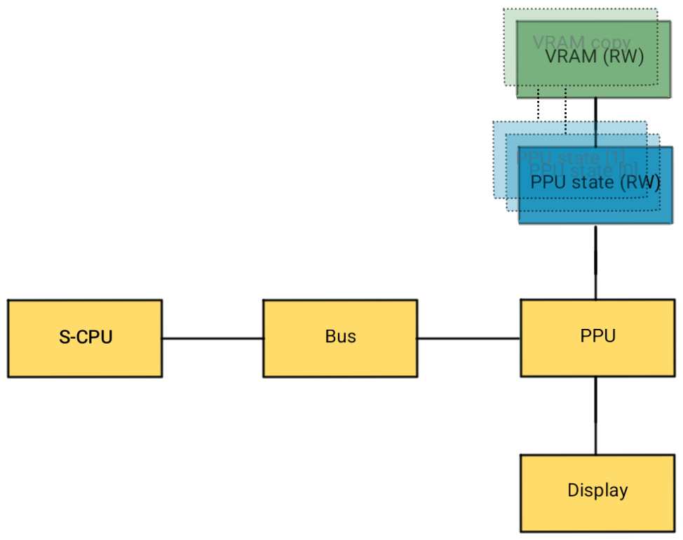
Now, whenever PPUState is cloned and sent off to a worker thread, only the
reference to VRAM is cloned along with it. Because of the use of Arc<T>,
the VRAM copy is dropped as soon as it is not used by any PPUState
anymore. This VRAM copy is immutable and therefore read-only.
At the end of VBlank, we can simply refresh the copy we’re using on newly
cloned PPUStates by updating the reference on the live state:
impl<TRenderer> Tickable for PPU<TRenderer>
where
    TRenderer: Renderer,
{
    fn tick(&mut self, ticks: Ticks) -> Result<()> {
        if self.get_current_scanline() != self.last_scanline {
            // Vertically progressed into a new scanline
            self.last_scanline = self.get_current_scanline();

            if self.in_vblank() {
                if !self.vblank {
					self.vblank = true;
					// ...
				} else {
                    self.vblank = false;

                    // Roll over the VRAM buffer so any changes during the last frame
                    // reflect in the next frame.
                    self.state.vram = Arc::new(self.vram.clone());

                    // Send frame to the screen
					// ...
                }

                // ...
            }

			// ...
		}
		// ...
	}
}
If it ever turns out there are games that update VRAM during the frame, we can perform the same rollover before dispatching the scanline to the worker threads after detecting a VRAM write.
Moving presentation to its own thread
Whenever the PPU finishes a frame, SDL is called to present the frame on the
display. Right now, we simply at the end of the frame in the PPU::tick()
function.
This has some drawbacks. If the presentation blocks for whatever reason, for example if the target running the emulator is using a slow software renderer or the GPU driver forcibly enables vertical sync. In any case: we don’t want the speed of presentation to influence the speed at which the emulator runs. If presentation lags behind, we’d rather simply drop the frame.
To do this, we replace the renderer attached to the PPU object with a new
ChannelRenderer. This renderer simply clones the display buffer and sends
it down a crossbeam channel:
/// Renders changes to screen
fn update(&mut self) -> Result<()> {
    let buffer = std::mem::replace(
        &mut self.displaybuffer,
        new_displaybuffer(self.width, self.height),
    );
    match self.sender.try_send(buffer) {
        Err(TrySendError::Full(_)) => Ok(()),
        e => Ok(e?),
    }
}
The channel has a queue depth of 1, so any time the frames are not consumed fast enough, new frames are simply dropped.
Then, we move the entire emulation process to its own thread and in the main thread we only await new frames to present or SDL events to happen:
loop {
    let frame = framereceiver.recv()?;
    display.update_from(Arc::clone(&frame))?;

    while let Some(event) = eventpump.poll() {
		// ...
	}
}
Reducing copies of the rest of the state
We are still copying quite a bit of state currently when dispatching a scanline to the worker threads. We’ve saved on the largest chunk (VRAM) but are still copying OAM, CGRAM and all the registers, which adds up to an estimate of 1KB.
To further reduce this, we can also keep a reference-counted copy of all registers and memory (except VRAM) and share a read-only copy in the same way as we’re doing for VRAM.
Then, whenever the CPU makes a change in registers, CGRAM or OAM, we just pull a new copy.
It still makes sense to keep the VRAM copy mechanism separate because that is a lot more data to copy and unlikely to change throughout the frame.
Batching scanlines
This also allows us to batch scanlines so one worker job contains multiple scanlines to be drawn. This reduces the amount of overhead time spent on dispatching new jobs. As soon as a register is written, the previous batch can be closed and dispatched. One batch should contain a maximum of 4-8 scanlines, otherwise the benefit of parallelization diminishes.