
I have been working on an emulator for early (Motorola 68000-powered) Macintosh computers. While implementing the disk drive, I noticed documentation was scattered and hard to find. Now that I have a working implementation, this post is my attempt to document everything in one place.
IWM: the disk drive controller
The 68000 CPU interfaces with the disk drive through a controller, called ‘IWM’ (Integrated Woz Machine, a reference to Apple co-founder Steve Wozniak, who designed it). This controller handles all the logic and analog signals to the drive itself and exposes them in a usable way to the CPU.
The IWM controller was originally designed for 5.25” drives for the Apple II but the implementation has been modernized for 3.5” drives and the Macintosh. Many elements are, however, still the same and will be familiar to those familiar with the Apple II. For example, the CA0/CA1/CA2 I/O lines were used in the Apple II to move the drive head, but have been repurposed for register access in the 3.5”/Macintosh version.
From the Macintosh Plus onwards, it can control up to two disk drives.
I/O
All IWM I/O lines are memory-mapped from the CPUs perspective. There are addresses to set and clear certain signals and read/write bytes from and to the controller. The table below outlines the addresses, their associated I/O line, their purpose and whether they enable or disable the line.
Note that the ‘HEADSEL’ line is not directly memory mapped but has to be toggled through the VIA (Register A, bit 5).
| Line | Enable address | Disable address | Purpose |
|---|---|---|---|
| CA0 | 0xDFE3FF |
0xDFE1FF |
Drive register selection |
| CA1 | 0xDFE7FF |
0xDFE5FF |
Drive register selection |
| CA2 | 0xDFEBFF |
0xDFE9FF |
Drive register selection |
| LSTRB | 0xDFEFFF |
0xDFEDFF |
Drive register write strobe |
| ENABLE | 0xDFF3FF |
0xDFF1FF |
Drive enable Required for many drive commands. |
| SELECT | 0xDFF7FF |
0xDFF5FF |
Drive select Selects internal (off) or external (on) disk drive. Note that the Mac 128K/512K can only address one drive, due to the PWM speed control. |
| Q6 | 0xDFFBFF |
0xDFF9FF |
Selects which IWM register to access |
| Q7 | 0xDFFFFF |
0xDFFDFF |
Selects which IWM register to access |
| HEADSEL | Through VIA | Through VIA | Two purposes: selects the drive head to read/write data from either side of the disk (in double-sided drives) and plays part in drive register selection. |
Note that either reading or writing any of these locations will affect the associated I/O line.
The Macintosh ROM will only ever access these addresses as bytes. Only the lower eight data lines of the 68000’s data bus are connected to the IWM, meaning it should only be accessed on byte addresses with the lowest address bit set.
In the event a less well behaved application attempts access to an even address, it is worth noting that:
- The 68000’s UDS and LDS lines are not connected to the IWM, meaning any byte-sized write will go through as if bit 0 is ignored for even addresses because the CPU outputs the byte on the lower as well as the upper eight data lines.
- Reads to even addresses will be undefined as the upper 8 data lines are not connected to the IWM.
IWM registers
Note the differentiation above between IWM and drive registers. The IWM registers are part of the controller. The drive registers are per-drive, however, they are queried through the IWM status register, as will be described later on.
The ENABLE, Q6 and Q7 lines together select which IWM register to write or query:
| ENABLE | Q6 | Q7 | Read/Write | Register addressed |
|---|---|---|---|---|
| on | off | off | R | Data register (reading track) |
| on | on | on | W | Data register (writing track) |
| on | on | off | R | Status register |
| on | off | on | R | Handshake register |
| off | on | off | W | Mode register |
Mode register
The mode register configures the operation of the IWM and is shared among all drives. Although this register is write-only, it can be read back as part of the status register.
The Macintosh will normally always set the mode to $1F during very early boot and never change it
during normal operation.
However, it is known that some applications may change the mode register as part of disk copy protection
(e.g. by changing the IWM clock speed).
To change the mode register, software would:
- Read the status register to confirm the mode needs changing,
- Access ‘ENABLE off’ (
0xDFF1FF), - Access ‘Q6 on’ (
0xDFFBFF), - Write the desired value to ‘Q7 on’ (
0xDFFFFF), - Read the status register to confirm the mode has changed. If not, start over.
The bits in the mode register are described below.
| Bit(s) | Description |
|---|---|
| 7-5 | Reserved/irrelevant |
| 4 | Clock speed 0 = 7 MHz, 1 = 8 MHz. |
| 3 | Bit cell timing 0 = slow (4 µs/bit), 1 = fast (2 µs/bit) |
| 2 | Spindle motor shutdown delay 0 = one second, 1 = none |
| 1 | Write handshake protocol 0 = synchronous, 1 = asynchronous |
| 0 | Data latch mode 0 = no latching, 1 = data latched on most significant bit set |
Status register and drive registers
The status register reports a few general controller status bits but also allows for reading 1-bit disk drive registers. To read the status register, software would do the following:
- Set ‘SELECT’ according to the drive to be queried,
- Set the CA0, CA1, CA2 and HEADSEL to select the desired drive register,
- Access ‘ENABLE on’ (
0xDFF3FF), - Access ‘Q6 on’ (
0xDFFBFF), - Read the status byte from ‘Q7 off’ (
0xDFFDFF).
The table below describes the bits in the status byte:
| Bit(s) | Description |
|---|---|
| 7 | SENSE The content of the drive register that was inquired |
| 6 | Reserved |
| 5 | ENABLE line status. 0 = enable off, 1 = enable on. |
| 4-0 | Same as bit 4-0 of the mode register. |
The table below shows a list of drive registers that can be queried:
| CA2 | CA1 | CA0 | HEADSEL | Register | Description |
|---|---|---|---|---|---|
| off | off | off | off | DIRTN | Head step direction 0 = track up, 1 = track down |
| off | off | off | on | CISTN | Disk inserted 0 = disk in drive, 1 = no disk |
| off | off | on | off | STEP | Head stepping in progress 0 = head stepping, 1 = head still |
| off | off | on | on | WRTPRT | Disk write protect status 0 = write protected, 1 = not write protected |
| off | on | off | off | MOTORON | Spindle motor running 0 = running, 1 = off |
| off | on | off | on | TKO | Head at track 0 0 = track 0, 1 = other track |
| off | on | on | on | TACH | Spindle motor tachometer 60 pulses/disk revolution (= 120 edges) |
| on | off | off | off | RDDATA0 | Live track data (1-bit), lower head |
| on | off | off | on | RDDATA1 | Live track data (1-bit), upper head |
| on | on | off | off | SIDES | Drive head count 0 = one head (single sided, 400K drive), 1 = two heads (double sided, 800K drive) |
| on | on | off | on | READY(?) | Disk ready (? unsure if correct) 0 = ready, 1 = not ready |
| on | on | on | off | INSTALLED | Disk drive installed 0 = installed, 1 = not installed |
| on | on | on | on | PRESENT/HD(?) | Disk drive installed (? unsure if correct) 0 = installed, 1 = not installed |
Drive commands / writing registers
Disk drives can also receive commands through a similar selection mechanism as above.
- Set ‘SELECT’ according to the drive to be commanded,
- Set the CA0, CA1, CA2 and HEADSEL to select the desired drive command,
- Access ‘ENABLE on’ (
0xDFF3FF), - Access ‘LSTRB on’ (
0xDFEFFF), - Access ‘LSTRB off’ (
0xDFEDFF) after a minimum of 1 µs (except EJECT).
The table below shows the possible drive commands:
| CA2 | CA1 | CA0 | HEADSEL | Command | Description |
|---|---|---|---|---|---|
| off | off | off | off | TRACKUP | Sets head movement direction to higher tracks |
| on | off | off | off | TRACKDN | Sets head movement direction to lower tracks |
| off | off | on | off | TRACKSTEP | Moves the drive head one track in the selected direction. A step may take up to 30 ms for the head to settle. If the destination track is in a different speed group, it can take up to 150 ms for the motor to reach the proper speed. |
| off | on | off | off | MOTORON | Enables the spindle motor. Note that the spindle motor will not actually run unless there is a disk in the drive. The motor will be running at the proper speed within 400 ms. |
| on | on | off | off | MOTOROFF | Stops the spindle motor. |
| on | on | on | off | EJECT | Ejects the disk. Note that the LSTRB signal must remain active for 750ms for the eject to occur.* |
*: the Macintosh Plus briefly asserts eject during boot for unknown reasons. This does not cause an actual eject on hardware, but re-emphasizes the need to observe the 750ms in an emulator.
Handshake register
The handshake register is used when writing data to the disk to synchronize the write timing between the IWM and the CPU. See ‘Write data register’ below on how the disk writing process works. To read the handshake register, software would do the following:
- Set ‘SELECT’ according to the drive to be queried,
- Access ‘ENABLE on’ (
0xDFF3FF), - Access ‘Q7 on’ (
0xDFFFFF), - Read the handshake byte from ‘Q6 off’ (
0xDFF9FF).
The table below describes the bits in the handshake byte:
| Bit(s) | Description |
|---|---|
| 7 | Ready for data (data register empty) 0 - not ready, 1 - ready |
| 6 | Buffer underrun (write completed) 0 - underrun occurred, 1 - no underrun |
| 5-0 | Reserved |
In an idle situation, where the disk is not being written, ‘ready for data’ is set and ‘underrun’ is clear.
Read data register
In latch mode (always enabled on Mac), while the drive motor is running, every bit that passes under the head is left-shifted into a shift register. When the IWM sees the most significant bit in this register is set, the contents are copied into the data register and the shift register is cleared. This mechanism works based on the fact that, in GCR encoding, any valid byte has the most significant bit set. If there was already a byte in the data register, that byte is lost.
Reading the data register clears it to 0. The data read from this register is raw, encoded track data. Decoding the bytes, locating the right sector, etc. is all done in software. To read the data register, software would:
- Set ‘SELECT’ according to the drive to be queried,
- Access ‘ENABLE on’ (
0xDFF3FF), - Access ‘Q7 off’ (
0xDFFDFF), - Read the data byte from ‘Q6 off’ (
0xDFF9FF).
Write data register
Writing to the write data register makes the drive write to the disk. The data register is a buffer for the write shift register. When the write shift register is empty, the content of the data register is copied to the shift register. From this point, the data register can be filled again.
As the drive head progresses over the track, bits from the shift register are shifted out (from the most significant bit) and written to the disk.
There are two flags in the handshake register that are used to keep the buffer filled and synchronize the write process:
- Ready for data: this flag is set as soon as the data register content is moved to the shift register, signalling that the write data register needs to be filled with the next byte.
- Underrun: if the shift register is empty and there is no new byte waiting in the data register, writing stops and the underrun flag is set.
Software would follow the following process to write to disk:
- Select the desired drive, enable drive motor, move to desired track,
- Wait for the correct track position to line up under the head,
- Write the next byte to write to the data register:
- Access ‘Q7 on’ (
0xDFFFFF), - Write the desired value to ‘Q6 on’ (
0xDFFBFF),
- Access ‘Q7 on’ (
- If there is data left to be written, wait for the ‘ready for data’ bit to be set, then return to step 3.
- If there is no data left, wait for underrun.
The disk format
Macintosh floppies use Group Coded Recording (GCR) encoding in 6-and-2 encoding. Tracks are divided in sectors. Every sector can store an effective number of 512 (logical) bytes.
Sectors contain headers called ‘address markers’. These markers are used to locate specific sectors on the track. They contain:
- A preamble pattern used to locate the start of a header,
- The sector number,
- The track number and disk side,
- The disk format -
$02for single-sided 400K disks,$22for double-sided 800K disks, - A checksum of the header,
- A few trailing bytes.
Drive speed and timing
Macintosh disk drives spin at a Constant Linear Velocity, meaning the speed in which the disk spins increases towards the inside of the disk. By reading the outer tracks at a lower speed, it was possible to store data bits more densely packed together. This allowed Macintosh computers to store 400KB on a single-sided diskette or 800K on a double-sided diskette, where a PC would only manage to store 360KB or 720KB of data.
The disadvantage of this technique was that there was no interoperability with PC diskettes possible, at all, even with software changes. For the Macintosh, this changed with the introduction of the ‘SuperDrive’ or ‘FDHD’ in 1988. First offered as an upgrade on the Macintosh II and Macintosh SE, the SuperDrive was composed of a new ‘SWIM’ (Super Woz Integrated Machine) disk drive controller IC and a new disk drive which could read and write both Macintosh CLV and PC CAV formatted diskettes. The Macintosh IIx, introduced in September 1988, was the first model to include the SuperDrive as standard.
Below, there’s a table which shows the varying drive speeds per track and the amount of physical (e.g. encoded) bits per track.
| Track range | Drive speed | Physical bits per track |
|---|---|---|
| 0 - 15 | ~402 rpm | 74640 |
| 16 - 31 | ~438 rpm | 68240 |
| 32 - 47 | ~482 rpm | 62200 |
| 48 - 63 | ~536 rpm | 55980 |
| 64 - 79 | ~603 rpm | 49760 |
The approximate amount of CPU cycles per disk bit can be calculated using:
clock_speed * 60 / track_rpm / bits_per_track
At 8 MHz, the drive head produces a new bit approximately every 16 cycles, regardless of the track.
Speed control in the early Macintosh
In the Macintosh 128K and 512K with the 400K disk drives, the speed of the spindle motor is controlled by software using a PWM signal that is written to the LSB of every 16-bit slot in the sound buffer.
At boot, the Macintosh ROM performs an initial calibration by setting the drive to two different speeds and reading back the tachometer signal (TACH register). This calibration deals with temperature and component variance in the drive and electronics. During system operation, the drive is frequently re-calibrated.
To calculate the PWM duty cycle from the data in the sound buffer, convert the lower 6 bits of each value using the following table (calculation from MAME):
 0,  1, 59,  2, 60, 40, 54,  3,
61, 32, 49, 41, 55, 19, 35,  4,
62, 52, 30, 33, 50, 12, 14, 42,
56, 16, 27, 20, 36, 23, 44,  5,
63, 58, 39, 53, 31, 48, 18, 34,
51, 29, 11, 13, 15, 26, 22, 43,
57, 38, 47, 17, 28, 10, 25, 21,
37, 46,  9, 24, 45,  8,  7,  6
Sum these over a period of 100 values, then calculate the index using:
sum / (count / 10) - 11
Clamp the resulting value to 0-399 and calculate the duty cycle percentage by dividing the result by 4.19.
The disk drive specifications state the following bounds for drive speed vs. duty cycle:
| 9.4% | 305 < V < 380 rpm |
| 91% | 625 < V < 780 rpm |
With this information, you can calculate the drive speed dictated by the driver in the Macintosh ROM.
Emulating the PWM speed control is required, the software will not initialize the disk drive successfully if it notices the drive does not respond to PWM changes during calibration. An improper implementation may simply lead to failure to read the boot disk but may also cause a ‘sad Mac’ with a division by zero error.

Speed control in the Macintosh Plus and onwards
On models with dual-sided (800K) drives and onwards, the drive speed is controlled by hardware. When emulating the IWM, as long as the speed per track group matches the table above, it should work.
The software side
The ROM contains a driver that talks to the IWM and disk drive, called ‘Sony’. The name likely chosen because Sony designed and manufactured the early Mac disk drives. This driver exposes the decoded sector data, upon which the filesystem layer is built.
The IWM supplies the CPU with the physical, encoded track data straight from the disk. Decoding the GCR-encoding, finding and parsing the sector headers, etc. is all handled by the driver software.
For emulation purposes, knowledge of the Sony driver is not strictly required. However, it helps tremendously when debugging issues.
ROM API functions
Below is a list of Sony driver functions exposed by the Macintosh 512K ROM and the purpose of the function I’ve been able to discover.
| Function | Purpose |
|---|---|
E_Sony_Open |
Initializes driver, enumerates disk drives |
E_Sony_Prime |
Sets up drive for reading/writing |
E_Sony_Control |
Drive control commands (e.g. eject etc) |
E_Sony_Status |
Drive status request |
E_Sony_Close |
Does nothing? |
P_Sony_FigTrkSpd |
Calibrates the drive speed using the tacho signal. |
P_Sony_DiskPrime |
Sets up drive for reading/writing |
P_Sony_RdAddr |
Reads and decodes an address mark |
P_Sony_RdData |
Reads and decodes sector data |
P_Sony_WrData |
Writes a sector |
P_Sony_Seek |
Seeks to a sector |
P_Sony_SetUpPoll |
See below (polling) |
P_Sony_Recal |
Recalls the head to track 0 |
P_Sony_Control |
Drive control commands |
P_Sony_WakeUp |
Yields the CPU to other tasks for some time |
P_Sony_ReSeek |
Seeks to a sector |
P_Sony_MakeSpdTbl |
Part of the drive calibration process |
Polling the SCC
Reading/writing in the Sony driver occurs in a critical section where interrupts are masked. To avoid losing serial data during this time, the driver will poll the SCC write request pin and read the serial data onto a stack. If there are too many serial events during this critical section, that stack may overflow.
Boot sequence and errors
The ROM attempts to load a piece of boot code from the disk into RAM, to which it will jump.
Below are a few errors I have encountered which may help in troubleshooting. In any case, it is very helpful to debug the ROM and see which Sony driver functions it goes through until it fails. Note that negative return values from these functions indicate errors.
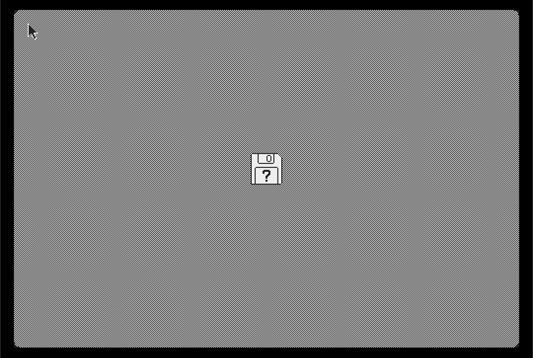
If you do not get the timing or IWM responses right in your emulator, you will likely get the crossed-out disk, which means that the ROM did not manage to load and execute the boot code from the disk:
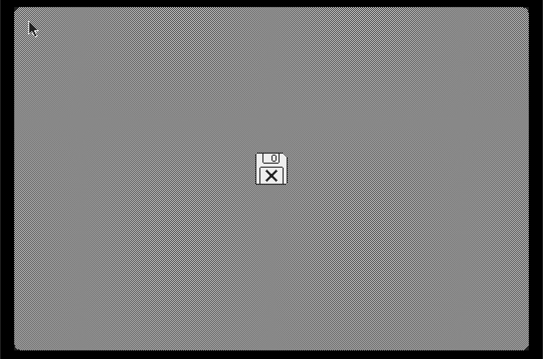
If the ROM bootstrap does manage to load and execute the boot code, but the boot code does not manage to find the second stage system file, you will get an ‘Invalid system disk’ sad Mac, like below. In that case, you may not be feeding the right track data.

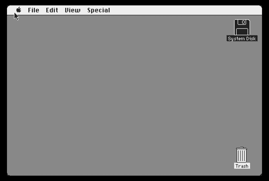
If everything works out, you should be greeted with the welcome screen, and finally, the desktop:

References
- Apple Computer, Inc - Guide to the Macintosh Family Hardware, 2nd edition
- Apple Computer, Inc - Inside Macintosh, volume III
- Apple Computer, Inc - 400KB disk drive specifications
- Apple Computer, Inc - Integrated Woz Machine (IWM) specification - 1982
- Neil Parker - Controlling the 3.5 Drive Hardware on the Apple IIGS - 1994